JULY 2021 RIDDLE ANSWERS

Growing Economy

Forgive and Forget

In between jobs

On cloud nine

Growing Economy
Forgive and Forget
In between jobs
On cloud nine
The third room is the safest because the lions would have died of starvation.
Equipotential bonding and earthing are essential parts of electrical safety. Both play an important part in preventing electrical shocks in your plant.
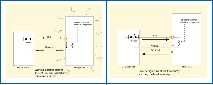
Electrical equipment requires earthing to ensure that if a fault occurs that the voltage has a safe path to travel where the surge in current will trip a breaker, cutting power to the equipment, making it safe to touch.
For example, if your fridge had a loose wire, that wire is live and if someone touched it, they would get an electric shock. The chances of touching the loose wire may seem slim, however if the fridge is not earthed and that wire touches the frame or body of the fridge, this would then cause the whole fridge to become ‘live’ meaning that if you walked up to the fridge and touched it you would be shocked or electrocuted.
The principal of earthing is to take that live current away, allowing it to travel down the electrical installation earthing path, where the surge in current trips a breaker supplying power to the fridge. This cuts all power to the fridge and makes it safe to touch.
morganinspectionservices.com
In addition to earthing electrical equipment further safety measures need to be taken to protect workers from the risk of electrical shock from other conductive equipment in your plant.
This is done by equipotential bonding. Equipotential bonding connects all accessible metalwork whether associated with the electrical installation (known as exposed metalwork) or not (extraneous metalwork) to the electrical service earth.
Within your building there will be many services that use metal connections including water pipes, gas piping, HVAC ducting and even the metal structure of the building itself. These can all provide a risk of current flowing through paths not designed to carry a path and create the risk of electrical shock for your workers.
Examples of what may require equipotential bonding as part of your electrical installation:
How does Equipotential bonding work?:
Equipotential bonding aims to limit the magnitude of touch voltages. Without equipotential bonding the risk is that the voltage flows between the ‘live’ electrical equipment and other conductive equipment in your plant – essentially making all metal parts in your plant ‘live’. If someone was to touch two of these things at the same time, they would create a circuit. Because of the difference in energy between the ‘live’ item and the other conductive equipment in your plant, energy would flow from the high potential point to the lower potential point as fast as possible via the connection (your worker). This could be fatal if the voltage is high enough. Equipotential translates to equal potential, so by bonding all the conductive parts it allows the potential (voltage) to be the same, reducing the risk.
Bonding is usually achieved with a large earth wire in good secure contact with the exposed extraneous conductive part(s) which is connected directly back to the main switchboards main earth bar and via this to the earth electrode. Equipotential bonding of earthed equipment ensures workers in an equipotential zone are protected because there is a nearly identical level of electrical potential between all points of the body.
Equipotential bonding also has a secondary goal of mitigating noise in the electrical network. Operation problems that can occur without effective equipotential bonding and grounding include:
EAS has the skills and experience to deliver high quality electrical solutions you can trust. If you’d like to find out more about ensuring the safety of your staff and equipment, get in touch with the EAS team today on 07 834 0505.
He was cleaning the windows on the inside of the building!
Copper with its corrosive resistance, electrical conductivity and superior heat transfer make it one of the most important metals in use today.
When it comes to the electrical industry, nearly all electrical wires and cables today use copper. This means that the increasing demand and pricing is having a significant impact on cable pricing.
What is driving these increases?
The demand for copper is increasing dramatically as worldwide economies ramp up with the roll out of vaccines. The increasing push by governments for sustainable energy generation is also contributing to demand with copper being the key metal in generation, transmission, storage and consumption of electricity.
As demand has continued to grow, unfortunately supply has not kept pace with the worldwide pandemic effecting production. International Copper Study Groups in Peru, the world’s second largest producer of copper, reported a 12.5% plunge in output in 2020. With demand increasing and supply constrained, copper prices are reaching highs not seen in many years.

Is this a short-term problem?
While the roll out of vaccines across the world should assist with increasing the supply of copper, the worldwide demand for copper is forecast to continue to grow. Some analysts are predicting that growth will be as much as 50% over the next ten years as the world moves to low carbon options. For example, the production of a petrol/diesel car uses 16kg of copper compared to an electric or hybrid car which requires 60kg.

What does this mean for you?
EAS quotes your jobs based on the current pricing for cable. While we have traditionally guaranteed this pricing for a period of 30 days, the constantly increasing copper prices and demand for stock means that we cannot always guarantee pricing for this length of time. If we are aware of an impending price increase, your quote validity may reduce, which gives you the opportunity to get your orders in before prices increase again.
In addition to the pressure on copper pricing, International shipping availability is also stretched which has resulted in approximately 20% less capacity and as much as a 50% increase in rates, further adding to unpredictability with sourcing materials.
We highly recommend if you have projects where a significant amount of cable will be required you confirm these as soon as possible so that we can lock in supply and pricing.
If you have any questions, don’t hesitate to get in touch with the team on 07 834 0505.
The Importance of Circuit Breaker Testing in Preventative Maintenance
Circuit breakers can often go for extended periods without activation. While their reliability is typically high, if they fail when activated, the consequences can be catastrophic.
Failures during activation may result in severe arc flash incidents, threatening the safety of your staff and your plant operations. Additionally, such failures can cause extensive and costly damage to your electrical systems. To prevent these issues, routine testing and maintenance of circuit breakers are critical.
Primary Injection Testing
Primary and secondary injection testing should be integral components of your preventative maintenance plan to ensure the reliability and safety of your power circuit breakers.
Why Primary Injection Testing?
Primary injection testing is often preferred because it encompasses the entire current path, including current sensors, wiring, and the breaker itself. This method provides a comprehensive check of the system’s functionality. However, it may not always detect issues related to sensor wiring and polarity, so additional inspections may be required.
How Does It Work?
In a primary injection test, a calculated amount of low voltage (typically 5 to 10 volts) is used to generate high current, which is then injected through the circuit breaker. The breaker’s trip response time is measured and compared to its time-current curve specifications. Each function of the breaker requires a specific testing current value with a corresponding acceptable time response to determine compliance.
Common Primary Injection Tests
Primary injection tests can be applied to a variety of systems, including:
Secondary Injection Testing
Secondary injection testing complements primary testing and is often performed first to minimise risks during initial assessments, particularly on the low-voltage side of the equipment.
What Does It Do?
Secondary injection testing focuses on the proper operation of protection controls downstream from the protection relays. Unlike primary injection testing, it does not involve high current flowing through the breaker’s line and load contacts. Instead, this method verifies the electronic trip functions and protection settings of the circuit breaker.
How Does It Work?
This type of testing usually involves disconnecting the trip unit from its normal circuitry and connecting it to specialized testing equipment. This equipment injects simulated signals, measures response times, and records the breaker’s operational characteristics. Secondary testing provides a safer and more accessible way to verify the electronic and functional integrity of circuit breakers.
Advantages of Secondary Injection Testing
The Critical Role of Preventative Maintenance
Incorporating both primary and secondary injection testing into your preventative maintenance program ensures the reliability and safety of your electrical systems. Regular testing helps:
Get Expert Support for Circuit Breaker Testing
If you need assistance incorporating primary and secondary injection testing into your preventative maintenance program, the EAS team is here to help. Our experienced professionals can provide tailored solutions to meet your facility’s needs. Contact us today at 07 834 0505 to ensure your circuit breakers are operating safely and reliably.
The yellow switch
Air Conditioning provides us with a comfortable working environment, where we believe we are breathing good clean air. However, there are many invisible pollutants in the air that we are often not aware of and the damage they are doing.
With the spread of Covid-19 around the globe, we have all become much more aware of the ease with which viruses transmit. The diagram below shows all the ways that viruses and bacteria can get into HVAC systems.
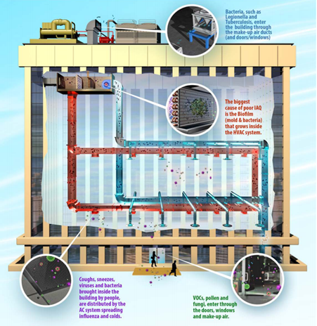
The biggest cause of poor indoor air quality is Biofilm.
Biofilm forms when mould and bacteria adhere to surfaces in moist environments by excreting a slimy glue-like substance which dust sticks to. The biofilm grows in the cooling coil and releases spores into the air stream. As Biofilm grows it forms a protective shell which traditional cleaners are unable to fully penetrate, making it difficult to remove. Biofilm is also a poor conductor of heat and therefore inhibits the cooling efficiency of the coil. In addition to Biofilm, indoor air quality is also reduced by the circulation of virus and bacteria contaminants brought into the building by people and from the outside air.
How can you improve indoor air quality?
Ultraviolet-C (UVC) light is a powerful tool for arresting the spread of unhealthy contaminants.
UVC inactivates the microbes, bacteria, viruses and mould by altering their DNA, destroying their ability to reproduce.

Source: Steril-Aire
With the correct number of emitters and UVC dose selected according to your cooling coil size and airflow up to 99% of the airborne biological pollutants can be destroyed. UVC will also eliminate the mould that keeps the biofilm attached to the fins of the cooling coil. The dead mould detaches from the metal fins and is washed into the drain pan by the condensate leaving the cooling coils clean.
Benefits of using UVC light sterilisers:
If you would like to find out more about installing UVC light sterilisers in your HVAC systems, get in touch with EAS today on 07 834 0505.
The circle = 3
The star = 5
The triangle = 4
for more puzzles check out briddles.com
What are bore pumps:
A bore is a hole drilled in the ground that fills up with groundwater which can then be pumped out to use for drinking water for animals and livestock or irrigating gardens and farms.
Groundwater is water found beneath the land in pores and fissures in rock and soil. A bore pump, either above ground or a submersible pump and motor, is used to pump the water up and out for a range of uses.
Care needs to be taken when selecting a location to install a bore pump, ensuring safe and clean drinking water. Contact the team at EAS to help provide insight on ways to protect your bore location.

Reliability:
These pumps are very low maintenance, generally with a 10-15 year lifespan, with the infrastructure supporting the pump around 20-30 years. Some of the pumps can be setup with certain parameters, allowing constant pressure and flow. They can be setup for various applications suiting either mains or low pressure systems.
If you have a bore pump water supply system that is faulting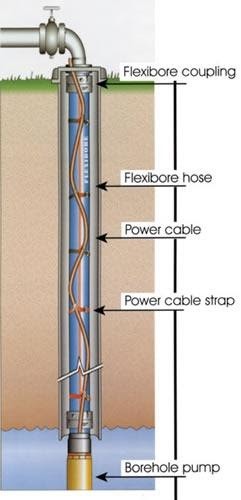
or causing issues, EAS can provide assistance with electrical testing and troubleshooting.
Power Supply:
Your pump will require electricity to power it. Some applications may require a purpose-built pumping shed, complete with appropriate distribution valving, UV filtering, control equipment, general power & lighting.
EAS can provide you with a complete solution to installing a water bore on your property; from coordinating the drilling to setting up and installing your pump to ensure it is protected from power surges – giving you a long-term solution to your water needs.
To find out more, get in touch with the team on 07 834 0505 or [email protected]