Puzzle Answer – February 2023

newsletter-lateral-thinking

Answer: Brian is a bus driver.

Puzzle Answers December 2022

2

Puzzle Answers October 2022

riddle-answer

Moving Towards a Greener Future

With the heatwave sweeping across Europe, climate change and its impacts on our environment are a hot topic of discussion. Also featuring regularly in our news stories are the increasing cost of living; highlighting the tricky balance everyone is trying to find – maintaining economic growth while reducing our consumption of energy and other natural resources to protect our environment.

The International Energy Agency (IEA) has identified that 37% of global energy use comes from industry and contributes 24% of CO2 emissions. A large proportion, approximately 70%, of this energy use is associated with electric motors.

Motors are found in so many applications:

  • Small motors are used in air conditioner and refrigerator compressors, computer printers and countless other devices.
  • Mid-sized motors are used in heating and ventilation systems as well as in pumps, conveyors, and fans.This group is where most of the electric power is consumed and where there is the greatest opportunity to improve efficiency. Many of these motors are bigger than required and are often run at full speed when the extra power is not required.
  • The largest electric motors are found in ship propulsion systems and heavy equipment used for mining and paper mills.

dyk

Three key actions which can improve the impact motors have on energy consumption and the environment are:

  1. Ensuring the motor is sized correctly for the application
    Motors are most efficient when operating between 60 – 100% of their full rated load. Simply buying the right sized motor can significantly increase efficiency.
  2.  Invest in a high efficiency motor
    motor-efficiency
    Note: Level 5, Ultra-premium efficiency motors are currently being developed by some manufacturers, however specified standards have yet to be put in place for these.It’s estimated that if 80% of today’s installed industrial motors were replaced with IE5, ultra-premium efficient motors, 160 terawatt-hours of energy per year would be saved, equivalent to more that the annual power consumption of Poland. (Source:  ABB White paper – Achieving the Paris Agreement)
  3. Utilising Variable Speed Drives (VSDs)
    Variable Speed Drives (VSD) control motor speed in response to varying process demands in your plant. The motor speed adjustment can be based on feedback from the process; for example, flow rate, temperature or pressure so that process control can be improved. This means that the electric motor will run only as fast as needed by the underlying load.Due to the ‘magic’ of affinity laws, small decreases in the speed of pumps and fans or the pressure of pumps can lead to large decreases in energy use meaning the use of VSDs can provide significant energy savings. For example:

    • Using a VSD to reduce the speed of a motor reduces energy consumption by around 50%.
    • Using a VSD to reduce the pressure of a pump by 20%, reduces the energy consumption by around 28%.

If you want to find out about moving to more energy efficient solutions for your plant, then get in touch with the EAS team today on 07 834 0505.
Fault Finding

  • Faults and breakdowns can cost your company a lot of time, and money. Finding the fault, and being able to repair it quickly and efficiently, is essential to minimising your downtime.

    Some of the common cause of industrial electrical faults include:

  • Open circuit faults. These types of faults are often easily identified as some part of the circuit will not be working as it’s not receiving the voltage required to operate correctly.  Burned out light bulbs, open operating coils, and loose connection or terminal points can be the cause of this type of fault.
  • Short circuit faults are more difficult to find and repair. Typically, a short circuit occurs when the insulation around a conductor deteriorates, and the current finds a path to another conductor or grounded object. This can cause fuses or circuit breakers to operate because of unwanted excessive current flow. The short circuit could also energise other parts of the circuit and cause other components to operate unintentionally.
  • Low voltage problems can cause relays to chatter or not pick up at all. Motors and components with coils can heat up more than normal and cause electrical insulation to deteriorate and possibly fail.
  • Over voltage problems generally shorten the lifespan of most components due to greater than normal heating. Lighting and motors are most affected by this problem.
  • Electro/mechanical faults usually happen to components that are nearing end of life or have manufacturing defects. This type of fault includes things like a pushbutton that no longer closes when pushed or a relay with stuck/welded contacts. This type of fault often shows no exterior signs of internal problems.

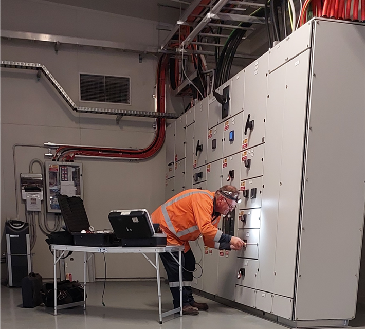
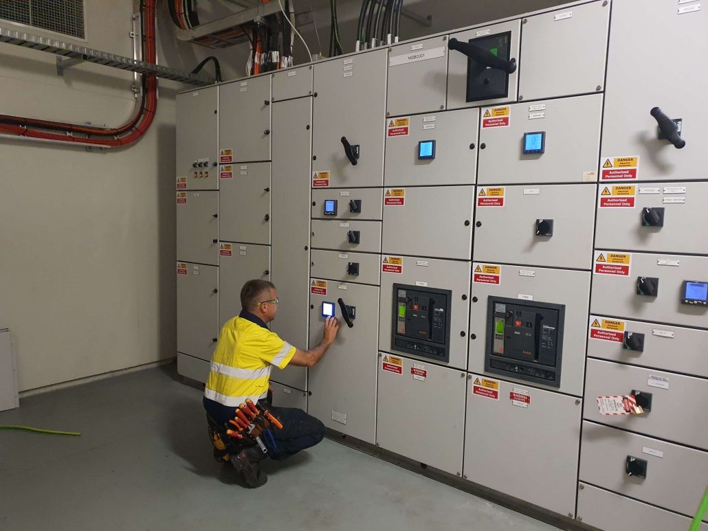
Electrical & Automation Solutions (EAS) uses a fault finding process to help identify the cause of electrical faults in your plant or process.

fault-finding-2

Step one:  Fact finding
The most useful first step in determining where a fault is usually begins with some basic fact finding such as identifying:

  • which equipment was running when the problem occurred?
  • is the equipment out of sequence or showing evidence of a fault?
  • does the operator think there is a fault? If so, what?
  • If any work been recently undertaken which could have created issues?
  • Before moving on to the next steps of troubleshooting the electrical fault, it is essential to understand the organisation’s safety rules and procedures, including the lockout/tagout rules and testing procedures.

    Step two: Observation
    This involves looking for visual signs of malfunctioning equipment including loose components, parts in the bottom of the cabinet, or signs of overheated components. All your senses can help in this process including smell, listening for abnormal sounds, and touching to feel for excessive heat or loose components. It is also a good idea to fully test operate equipment if possible, and note what is working correctly and what is not.

    Step three: Define Problem Areas
    Steps one and two should identify which parts of the circuit are operating correctly and which are not. Any properly functioning parts of the circuit can be eliminated from the problem areas, decreasing the testing time required later.

    Step four: Identify Possible Causes
    Once the likely problem area is identified we can then begin to list probable causes and their likelihood. Possibilities could include blown fuses, mechanical components, windings and coils, terminal connections, and wiring.

    Step five: Test Probable Cause
    Test the likely cause starting with the most probably cause. A range of tools can be used to assist with this including:

  • A voltmeter
    This is used to check the volts coming into and out of the equipment. A voltmeter measures AC or DC volts in a circuit and is preferred for finding open circuits.
  • Clip-on ammeter
    This measures current draw of components while they are operating. A motor that is drawing more current than normal may have worn bearings or could be overloaded. The clip-on ammeter is also useful for determining current flows in different parts of a circuit.
  • Ohmmeter
    An ohmmeter measures resistance in a circuit and is a great tool for finding short circuits, open coils, or burned out light bulbs.
  • Thermal imaging
    Thermal imaging can be used to see if components inside machinery and systems are over-heating or under-heating. It can also see if they are taking longer than usual to heat up, and get going, or if they are heating up too quickly. Any of these can indicate exactly where the issue is, and also helps to make an informed opinion about the nature of the problem or issue.

From your tests you may need to sectionalise the circuit further to reduce the problem area. Continue with this method until you find a suspect component or wire.

Step six: Replace Component and Test Operate
Once the defective component is identified, it should be replaced, and test operation of the complete circuit should be undertaken. If everything is operating correctly, the equipment can return to service. If the circuit still doesn’t operate correctly, you will need to work through the fault finding process from the start again.
The Electrical & Automation Solutions team love tough problems and taking on the challenge of finding faults.  We will work with you to ensure the fault finding and fixing of your electrical problem is as seamless as possible minimising your downtime and getting your plant or process is up and running as quickly as possible.  

August 2022 Riddle Answer

Screwdriver = 3

Sun = 5

Ute =  7


Answer = 22

Vibration Monitoring

While all machinery vibrates, monitoring vibration is vital to detecting machine damage in a timely manner to prevent costly break-downs.

Unexpected equipment failures can be expensive and potentially catastrophic, resulting in unplanned production downtime, costly replacement of parts and safety and environmental concerns. 

Vibration monitoring transmitters and sensors use accelerometers to measure changes in amplitude, frequency, and intensity of forces that damage rotating equipment. Studying these vibration measurements allows you to discover imbalance, looseness, misalignment, or bearing wear in equipment before it fails.
Vibration analysis can improve your maintenance and reliability programme by:
  • Finding a developing problem that can be repaired to increase the lifespan of your machine.
    Vibration can prematurely wear components and shorten the lifespan of equipment, create noise and result in safety issues. Imbalance or misalignment in rotating assets may crack or break driveshafts or other components.
  • Detecting and monitoring a chronic problem than cannot be repaired and will only get worse.
  • Establishing acceptance testing criteria to ensure that installation/repairs are properly conducted.
  • 24/7 continuous vibration monitoring can be used to predict failures as part of a predictive maintenance programme.
What should be monitored for vibration?
  • Motor Vibration Monitoring
    Motors generally experience high vibration levels at some point. Vibration monitoring can help pick up faults related to motor bearings, gearboxes and rotors.
  • Bearing Condition Monitoring
    Bearing defects are often the cause of vibration in machinery Bearing defects can include excessive loads, true or false brinelling, overheating, reverse loading, normal fatigue failure, corrosion, loose or tight fits and misalignment. Vibration monitoring can help pick up these problems and help determine if repair or replacement is required.
  • Gearbox Vibration Monitoring
    Impacting and friction can occur in gearboxes. A single crack in a gear could cause a change in speed once the defective teeth are inside the load zone.  This will result in impacting, and if there is insufficient lubrication for the gear teeth, friction will also occur.  Vibration monitoring can help detect impacting and friction.
  • Rotor Vibration Monitoring
    Lateral vibrations can occur in rotors, including instability and unbalance along with other types of forces impacting the rotor. Cracks are often formed, leading to reduced natural frequencies as a result of reduced rigidness. Rotor vibration analysis can monitor the rotor’s behaviour and help locate a crack.
If you would like to have vibration testing conducted at your plant either as a one off assessment or as part of a regular preventative maintenance plan, then get in touch with the Electrical & Automation solutions (EAS) team today on 07 834 0505. 

July 2022 Riddle Answer

Honey!

MOTOR SELECTION

A motor is used to convert electrical energy into mechanical energy to power a range of processes from simple functions like powering a fan to industrial operations such as pumps, conveyors or agitators.

Motors differ according to their power type (AC or DC) and their method of generating rotation. AC motors are used to drive complex and more fragile equipment, whereas DC motors usually power heavier equipment that needs easier maintenance and operation controls. AC motors can also provide higher levels of torque, which means they are often considered more powerful than DC motors.

There are various types of both AC and DC motors.

motors


MOTOR TYPES – DC MOTORS

Brushed DC motors
Brushed DC motors have a simple design and are easy to control. While they are used in a range of consumer goods such as small appliances, they can also be suitable for industrial applications where high torque is required. For example, dispensing equipment used in the medical and packaging fields.

The disadvantage of brushed DC motors is that the brushes and commutators tend to wear relatively quickly. Their continuous contact means they require frequent replacement and periodic maintenance.


Brushless DC Motors:
As the name suggests, Brushless DC Motors (BLDC) do not use brushes. Instead, the rotor is a permanent magnet. The coils do not rotate but are instead fixed in place on the stator. Because the coils do not move there is no need for brushes and a commutator.

The permanent magnet rotates by changing the direction of the magnetic fields generated by the surrounding stationary coils. To control the rotation, you adjust the magnitude and direction of the current into these coils.

Brushless DC Motors are used in industrial applications where precise motion control and stable control are critical. These include:

  • Linear motors
  • Servomotors
  • Actuators for industrial robots
  • Extruder drive motors
  • Feed drives for CNC machine tools

Stepper Motors:
Stepper motors are driven by pulses. They rotate through a specific angle or step with each pulse. Because the rotation is precisely controlled by the number of pulses received, these motors are widely used to implement positional adjustments.

Examples of the types of industrial applications they may be used for include:

  • printing presses
  • medical imaging machinery
  • CNC milling machines.


MOTOR TYPES – AC MOTORS:

Induction Motors:
An induction motor is an AC electric motor. The electric current in the rotor needed to produce torque is obtained via electromagnetic induction from the rotating magnetic field of the stator winding.

Induction motors are the most frequently used type of motor. They are used in residential, commercial, and industrial settings, with over 80% of all motors being induction motors.

Induction motors are also known as Asynchronous Motors. This is because an induction motor always runs at a slower speed than synchronous speed. The speed of the rotating magnetic field in the stator is called synchronous speed.

There are two main types of AC induction motor: single-phase and three-phase.

Single-phase induction motors are used extensively for smaller loads, such as household appliances like fans. While these motors have traditionally been used in fixed-speed applications, they are increasingly being used with variable-frequency drives (VFD).

Single-phase Induction Motors are used for:

  • Pumps
  • Compressors
  • Small fans
  • Drilling machines

Industrial applications generally require three-phase motors. A three-phase AC motor has three main stator windings and operates on three-phase AC power. Three-phase motors are self-starting and can produce a large initial torque. AC induction motors for industrial applications range in size from 1 to 100,000 hp.

Most three-phase motors have squirrel cage rotors, but they can also have wound rotors. Squirrel cage motors are more widely used as they have a simple design and rugged construction. This rugged construction means they require little maintenance which makes them a popular choice for domestic and industrial appliances.

Three Phase Induction Motor are used for:

  • Lifts
  • Cranes
  • Hoists
  • Large capacity exhaust fans
  • Driving lathe machines
  • Crushers
  • Oil extracting mills
  • Textile and etc.

Synchronous Motors:
In synchronous AC motors the rotor rotates in sync with the excitation field. The magnetisation of the rotor is produced by a permanent magnet in brushless designs or by windings with an AC current supplied through slip rings or brushes.

These motors maintain a constant speed at all loads. When the load exceeds the rated load, the motor ‘pulls out’ of synchronism and will stop operating. Synchronous motors are suitable for precision drives where accurate speed control is required.

The advantages of the synchronous motor are the ease with which the power factor can be controlled and the constant rotational speed of the machine, irrespective of the applied load.

Synchronous motors are used in:

  • Belt driven reciprocating compressors
  • Centrifugal pumps
  • Various industrial mills


WHAT TO CONSIDER WHEN PURCHASING A MOTOR:

There are many aspects to consider when selecting an industrial motor. These include:

  • The industrial application
    How the motor will be used and any special considerations such as the physical space in which the motor needs to operate.
  • Current:
    Current is what powers the motor and too much current will damage the motor. For DC motors both operating and stall current are important.
  • Voltage:
    The voltage rating of a DC motor indicates its most efficient voltage while running. If too few volts are applied the motor will not work, whereas if too many volts can short windings resulting in power loss or complete destruction.
  • Torque:
    Operating and stall values also need to be considered with torque. Operating torque is the amount of torque the motor was designed to give and stall torque is the amount of torque produced when power is applied from stall speed.
  • Velocity:
    The general rule is that motors run most efficiently at the highest speeds, but it is not always possible if gearing is required. Adding gears will reduce the efficiency of the motor, so you need to consider speed and torque reduction as well when selecting the appropriate motor.
  • Environment:
    Most motors are designed to work in clean, dry, room temperature environments. If the motor is likely to be exposed to dust or water contamination or will be required to run at high temperatures than the motor options will be more limited.

Other considerations also include

  • Does the application require a constant or variable speed?
  • Is position control required for the application?
  • What is the load and is it continuous or intermittent duty?

Selecting, installing, and maintaining the right motors in your company’s facilities and equipment is an essential step to ensuring uninterrupted operation and production.

Electrical & Automation Solutions (EAS) can provide you with advice on the right motor for your process as well as provide you with ongoing maintenance and service to ensure they continue to run in top notch condition – get in touch today!