May 2023 – Riddle Answer

Q:  What has a heart but doesn’t beat?

A:  An artichoke

Thermal Imaging Checks

One of the tricky things about electrical systems is that you often can’t see faults without taking things apart.

thermography2

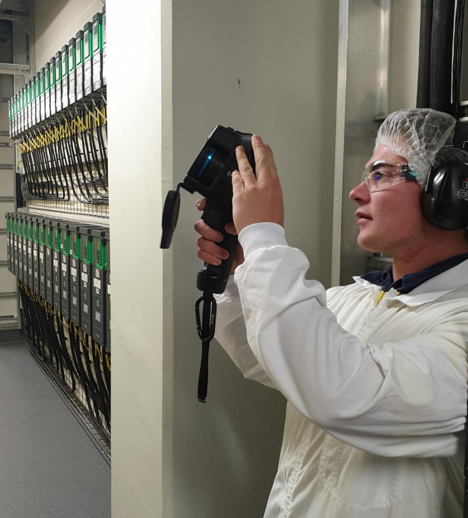
Thermal imaging or thermography is a non-intrusive, non-contact method of detecting electrical faults that are hidden to the naked eye.  During a thermal imaging survey, we use our specialised camera to capture images of the heat energy emitted by your electrical equipment.

The thermal camera measures the temperature of the electrical components and creates an image that shows the temperature distribution across the surface of the equipment
Thermal imaging should be an important part of your preventative maintenance plan as these checks can indicate faults that you may be completely unaware of before they become a serious problem. Heat is often an early symptom of equipment damage or malfunction, and by detecting these problems early, corrective action can be taken before the damage becomes more extensive reducing the risk of equipment failure, reducing the costs of reactive maintenance and unplanned downtime and it can also help extend the lifespan of your assets.

Thermography checks should be performed regularly as part of your routine maintenance plan, however other events can also mean a thermography check should be done, including:

  • after any major changes or upgrades to the electrical system
  • if there are signs of overheating or burning smells coming from your electrical equipment
  • if there have been any electrical system failures or intermittent faults
  • if there has been a power surge or electrical storm which may have caused damage to the electrical system.

Thermal imaging can be used to check:

  • Electrical panels
    to detect hot spots caused by loose connections, overloading, or other issues that may lead to equipment failure or fire hazards.
  • Circuit breakers
    to detect hot spots caused by overload or faulty operation, which may result in equipment failure or electrical fires.
  • Motors
    to monitor the temperature of bearings, windings, and other components to detect signs of wear or damage that may lead to equipment failure.
  • Switches
    to detect hot spots caused by overload or faulty operation, which may result in equipment failure or electrical fires.
  • UPS systems
    to monitor the temperature of batteries, components, and wiring to detect signs of wear or damage that may lead to equipment failure or power interruptions.
  • Generators
    to monitor the temperature of bearings, windings, and other components to detect signs of wear or damage that may lead to equipment failure.

The EAS team are trained and highly skilled in carrying out thermal imaging. To book a thermal imaging check of your vital equipment get in touch with the EAS team today on 07 834 0505.

Protecting your essential equipment with an uninterruptable power supply (UPS)

An Uninterruptible Power Supply (UPS) provides emergency power when the power source or mains power fails. A UPS differs from an emergency power system or standby generator in that it provides near instantaneous protection from power interruptions by supplying energy stored in batteries, supercapacitors or flywheels. The on-battery run time of most UPS is generally short (minutes rather than hours) but is sufficient to start a standby power source or properly shut down the equipment.

A UPS is designed to protect your vulnerable, and often expensive hardware from physical or memory-based damage if they’re suddenly disconnected from mains power. UPS’ are typically used to protect hardware such as computers, data centres, telecommunication equipment or other essential electrical equipment such as emergency lighting or alarm systems.

While a UPS’ main role is to provide short-term power when there is a power failure, most UPS units can also, in varying degrees, correct common utility power problems such as voltage spikes, sustained over voltage or momentary or sustained reduction in input voltage

What size UPS do I need?

Any UPS you install must be large enough to support all the equipment plugged into it. This means you need to calculate the load required. The load is the total amount of power drawn in watts of all the devices that are or will be plugged into the UPS. Once you know the load, you can select a UPS with the right capacity for your needs. The capacity is how much power a UPS can provide (measured in watts) if needed.

The runtime required in the event of power outage will also determine the size UPS you need. Runtime is the number of minutes a UPS can support the attached devices during a blackout. The minimum runtime should be the time needed to complete proper equipment shutdown.

The smaller the wattage load connected to the UPS the longer the batteries will last. To determine the runtime you need, start with the number of minutes required to completely shut down the connected devices. If a long runtime is required you can upsize your UPS so the connected load is a smaller percentage of the capacity or, with some UPS units, you have the ability to add additional battery modules to extend the runtime.

Different types of UPS

  • A Standby UPS is an offline unit that can detect a mains power failure and switch to battery power automatically. In normal operation the load is fed directly by mains power.
  • A Line-interactive UPS conditions the mains power by regulating input voltage up or down in a buck-boost transfer, before allowing it to pass through to your protected equipment. In the event of a mains power failure, battery power is provided automatically.
  • An on-line UPS converts power twice. First an input rectifier converts AC power into DC and feeds it to an output inverter. The output inverter then converts the power back to AC before sending it on to the protected equipment. This double conversion process insulates critical loads from dirty mains power completely to ensure that the connect equipment receives only clean reliable electricity.

UPS Maintenance

UPS’ should be regularly maintained to ensure that they are ready to function when you need them. Investing in a planned maintenance programme for your UPS can improve both reliability and the overall lifespan of your system. A well maintained and regularly serviced UPS needs less power to run, as well as being far less likely to fail and cause critical downtimes.

Preventative Maintenance Checks for your UPS:

  • internal and external checks
  • calibration of all metering and protective features if required
  • functional testing of all transfer conditions
  • inspection of on-line performance of equipment with load
  • visual check of batteries and battery environment
  • testing of battery voltage.

The EAS are highly skilled in sizing, installing and maintaining Uninterruptable Power Supplies (UPS). If you would like to discuss protecting your essential equipment with a UPS get in touch with the EAS team today on 07 834 0505 or [email protected].

Puzzle Answer – March 2023

The answer is 46:


7×10=70

4×6=24

70-24=46

maths-riddle-answer

Puzzle Answer – February 2023

newsletter-lateral-thinking

Answer: Brian is a bus driver.

Puzzle Answers December 2022

2

Puzzle Answers October 2022

riddle-answer

Moving Towards a Greener Future

With the heatwave sweeping across Europe, climate change and its impacts on our environment are a hot topic of discussion. Also featuring regularly in our news stories are the increasing cost of living; highlighting the tricky balance everyone is trying to find – maintaining economic growth while reducing our consumption of energy and other natural resources to protect our environment.

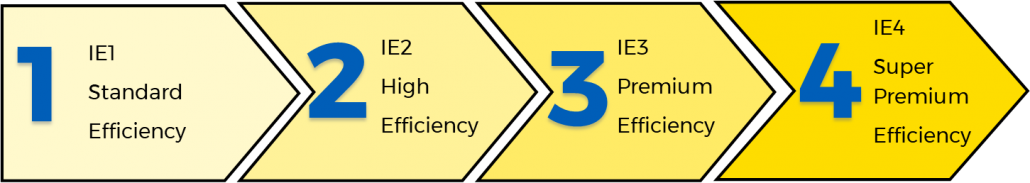
The International Energy Agency (IEA) has identified that 37% of global energy use comes from industry and contributes 24% of CO2 emissions. A large proportion, approximately 70%, of this energy use is associated with electric motors.

Motors are found in so many applications:

  • Small motors are used in air conditioner and refrigerator compressors, computer printers and countless other devices.
  • Mid-sized motors are used in heating and ventilation systems as well as in pumps, conveyors, and fans.This group is where most of the electric power is consumed and where there is the greatest opportunity to improve efficiency. Many of these motors are bigger than required and are often run at full speed when the extra power is not required.
  • The largest electric motors are found in ship propulsion systems and heavy equipment used for mining and paper mills.

dyk

Three key actions which can improve the impact motors have on energy consumption and the environment are:

  1. Ensuring the motor is sized correctly for the application
    Motors are most efficient when operating between 60 – 100% of their full rated load. Simply buying the right sized motor can significantly increase efficiency.
  2.  Invest in a high efficiency motor
    motor-efficiency
    Note: Level 5, Ultra-premium efficiency motors are currently being developed by some manufacturers, however specified standards have yet to be put in place for these.It’s estimated that if 80% of today’s installed industrial motors were replaced with IE5, ultra-premium efficient motors, 160 terawatt-hours of energy per year would be saved, equivalent to more that the annual power consumption of Poland. (Source:  ABB White paper – Achieving the Paris Agreement)
  3. Utilising Variable Speed Drives (VSDs)
    Variable Speed Drives (VSD) control motor speed in response to varying process demands in your plant. The motor speed adjustment can be based on feedback from the process; for example, flow rate, temperature or pressure so that process control can be improved. This means that the electric motor will run only as fast as needed by the underlying load.Due to the ‘magic’ of affinity laws, small decreases in the speed of pumps and fans or the pressure of pumps can lead to large decreases in energy use meaning the use of VSDs can provide significant energy savings. For example:

    • Using a VSD to reduce the speed of a motor reduces energy consumption by around 50%.
    • Using a VSD to reduce the pressure of a pump by 20%, reduces the energy consumption by around 28%.

If you want to find out about moving to more energy efficient solutions for your plant, then get in touch with the EAS team today on 07 834 0505.

Fault Finding

  • Faults and breakdowns can cost your company a lot of time, and money. Finding the fault, and being able to repair it quickly and efficiently, is essential to minimising your downtime.

    Some of the common cause of industrial electrical faults include:

  • Open circuit faults. These types of faults are often easily identified as some part of the circuit will not be working as it’s not receiving the voltage required to operate correctly.  Burned out light bulbs, open operating coils, and loose connection or terminal points can be the cause of this type of fault.
  • Short circuit faults are more difficult to find and repair. Typically, a short circuit occurs when the insulation around a conductor deteriorates, and the current finds a path to another conductor or grounded object. This can cause fuses or circuit breakers to operate because of unwanted excessive current flow. The short circuit could also energise other parts of the circuit and cause other components to operate unintentionally.
  • Low voltage problems can cause relays to chatter or not pick up at all. Motors and components with coils can heat up more than normal and cause electrical insulation to deteriorate and possibly fail.
  • Over voltage problems generally shorten the lifespan of most components due to greater than normal heating. Lighting and motors are most affected by this problem.
  • Electro/mechanical faults usually happen to components that are nearing end of life or have manufacturing defects. This type of fault includes things like a pushbutton that no longer closes when pushed or a relay with stuck/welded contacts. This type of fault often shows no exterior signs of internal problems.

Electrical & Automation Solutions (EAS) uses a fault finding process to help identify the cause of electrical faults in your plant or process.

fault-finding-2

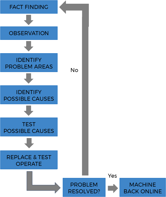
Step one:  Fact finding
The most useful first step in determining where a fault is usually begins with some basic fact finding such as identifying:

  • which equipment was running when the problem occurred?
  • is the equipment out of sequence or showing evidence of a fault?
  • does the operator think there is a fault? If so, what?
  • If any work been recently undertaken which could have created issues?
  • Before moving on to the next steps of troubleshooting the electrical fault, it is essential to understand the organisation’s safety rules and procedures, including the lockout/tagout rules and testing procedures.

    Step two: Observation
    This involves looking for visual signs of malfunctioning equipment including loose components, parts in the bottom of the cabinet, or signs of overheated components. All your senses can help in this process including smell, listening for abnormal sounds, and touching to feel for excessive heat or loose components. It is also a good idea to fully test operate equipment if possible, and note what is working correctly and what is not.

    Step three: Define Problem Areas
    Steps one and two should identify which parts of the circuit are operating correctly and which are not. Any properly functioning parts of the circuit can be eliminated from the problem areas, decreasing the testing time required later.

    Step four: Identify Possible Causes
    Once the likely problem area is identified we can then begin to list probable causes and their likelihood. Possibilities could include blown fuses, mechanical components, windings and coils, terminal connections, and wiring.

    Step five: Test Probable Cause
    Test the likely cause starting with the most probably cause. A range of tools can be used to assist with this including:

  • A voltmeter
    This is used to check the volts coming into and out of the equipment. A voltmeter measures AC or DC volts in a circuit and is preferred for finding open circuits.
  • Clip-on ammeter
    This measures current draw of components while they are operating. A motor that is drawing more current than normal may have worn bearings or could be overloaded. The clip-on ammeter is also useful for determining current flows in different parts of a circuit.
  • Ohmmeter
    An ohmmeter measures resistance in a circuit and is a great tool for finding short circuits, open coils, or burned out light bulbs.
  • Thermal imaging
    Thermal imaging can be used to see if components inside machinery and systems are over-heating or under-heating. It can also see if they are taking longer than usual to heat up, and get going, or if they are heating up too quickly. Any of these can indicate exactly where the issue is, and also helps to make an informed opinion about the nature of the problem or issue.

From your tests you may need to sectionalise the circuit further to reduce the problem area. Continue with this method until you find a suspect component or wire.

Step six: Replace Component and Test Operate
Once the defective component is identified, it should be replaced, and test operation of the complete circuit should be undertaken. If everything is operating correctly, the equipment can return to service. If the circuit still doesn’t operate correctly, you will need to work through the fault finding process from the start again.
The Electrical & Automation Solutions team love tough problems and taking on the challenge of finding faults.  We will work with you to ensure the fault finding and fixing of your electrical problem is as seamless as possible minimising your downtime and getting your plant or process is up and running as quickly as possible.