
Fault Finding
- Faults and breakdowns can cost your company a lot of time, and money. Finding the fault, and being able to repair it quickly and efficiently, is essential to minimising your downtime.
Some of the common cause of industrial electrical faults include:
- Open circuit faults. These types of faults are often easily identified as some part of the circuit will not be working as it’s not receiving the voltage required to operate correctly. Burned out light bulbs, open operating coils, and loose connection or terminal points can be the cause of this type of fault.
- Short circuit faults are more difficult to find and repair. Typically, a short circuit occurs when the insulation around a conductor deteriorates, and the current finds a path to another conductor or grounded object. This can cause fuses or circuit breakers to operate because of unwanted excessive current flow. The short circuit could also energise other parts of the circuit and cause other components to operate unintentionally.
- Low voltage problems can cause relays to chatter or not pick up at all. Motors and components with coils can heat up more than normal and cause electrical insulation to deteriorate and possibly fail.
- Over voltage problems generally shorten the lifespan of most components due to greater than normal heating. Lighting and motors are most affected by this problem.
- Electro/mechanical faults usually happen to components that are nearing end of life or have manufacturing defects. This type of fault includes things like a pushbutton that no longer closes when pushed or a relay with stuck/welded contacts. This type of fault often shows no exterior signs of internal problems.
Electrical & Automation Solutions (EAS) uses a fault finding process to help identify the cause of electrical faults in your plant or process.
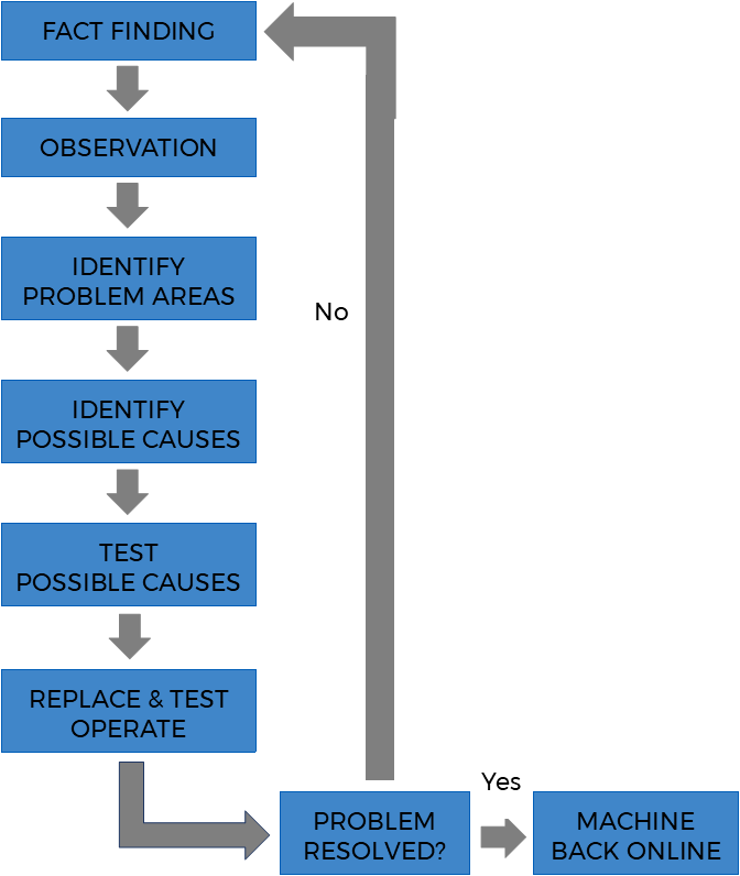
Step one: Fact finding
The most useful first step in determining where a fault is usually begins with some basic fact finding such as identifying:
- which equipment was running when the problem occurred?
- is the equipment out of sequence or showing evidence of a fault?
- does the operator think there is a fault? If so, what?
- If any work been recently undertaken which could have created issues?
- Before moving on to the next steps of troubleshooting the electrical fault, it is essential to understand the organisation’s safety rules and procedures, including the lockout/tagout rules and testing procedures.
Step two: Observation
This involves looking for visual signs of malfunctioning equipment including loose components, parts in the bottom of the cabinet, or signs of overheated components. All your senses can help in this process including smell, listening for abnormal sounds, and touching to feel for excessive heat or loose components. It is also a good idea to fully test operate equipment if possible, and note what is working correctly and what is not.Step three: Define Problem Areas
Steps one and two should identify which parts of the circuit are operating correctly and which are not. Any properly functioning parts of the circuit can be eliminated from the problem areas, decreasing the testing time required later.Step four: Identify Possible Causes
Once the likely problem area is identified we can then begin to list probable causes and their likelihood. Possibilities could include blown fuses, mechanical components, windings and coils, terminal connections, and wiring.Step five: Test Probable Cause
Test the likely cause starting with the most probably cause. A range of tools can be used to assist with this including: - A voltmeter
This is used to check the volts coming into and out of the equipment. A voltmeter measures AC or DC volts in a circuit and is preferred for finding open circuits. - Clip-on ammeter
This measures current draw of components while they are operating. A motor that is drawing more current than normal may have worn bearings or could be overloaded. The clip-on ammeter is also useful for determining current flows in different parts of a circuit. - Ohmmeter
An ohmmeter measures resistance in a circuit and is a great tool for finding short circuits, open coils, or burned out light bulbs. - Thermal imaging
Thermal imaging can be used to see if components inside machinery and systems are over-heating or under-heating. It can also see if they are taking longer than usual to heat up, and get going, or if they are heating up too quickly. Any of these can indicate exactly where the issue is, and also helps to make an informed opinion about the nature of the problem or issue.
From your tests you may need to sectionalise the circuit further to reduce the problem area. Continue with this method until you find a suspect component or wire.
Step six: Replace Component and Test Operate
Once the defective component is identified, it should be replaced, and test operation of the complete circuit should be undertaken. If everything is operating correctly, the equipment can return to service. If the circuit still doesn’t operate correctly, you will need to work through the fault finding process from the start again.
The Electrical & Automation Solutions team love tough problems and taking on the challenge of finding faults. We will work with you to ensure the fault finding and fixing of your electrical problem is as seamless as possible minimising your downtime and getting your plant or process is up and running as quickly as possible.
Leave a Reply
Want to join the discussion?Feel free to contribute!