Equipotential bonding and earthing are essential parts of electrical safety. Both play an important part in preventing electrical shocks in your plant.
Electrical equipment requires earthing to ensure that if a fault occurs that the voltage has a safe path to travel where the surge in current will trip a breaker, cutting power to the equipment, making it safe to touch.
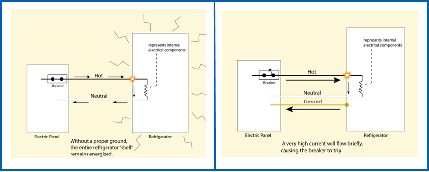
For example, if your fridge had a loose wire, that wire is live and if someone touched it, they would get an electric shock. The chances of touching the loose wire may seem slim, however if the fridge is not earthed and that wire touches the frame or body of the fridge, this would then cause the whole fridge to become ‘live’ meaning that if you walked up to the fridge and touched it you would be shocked or electrocuted.
The principal of earthing is to take that live current away, allowing it to travel down the electrical installation earthing path, where the surge in current trips a breaker supplying power to the fridge. This cuts all power to the fridge and makes it safe to touch.
morganinspectionservices.com
In addition to earthing electrical equipment further safety measures need to be taken to protect workers from the risk of electrical shock from other conductive equipment in your plant.
This is done by equipotential bonding. Equipotential bonding connects all accessible metalwork whether associated with the electrical installation (known as exposed metalwork) or not (extraneous metalwork) to the electrical service earth.
Within your building there will be many services that use metal connections including water pipes, gas piping, HVAC ducting and even the metal structure of the building itself. These can all provide a risk of current flowing through paths not designed to carry a path and create the risk of electrical shock for your workers.
Examples of what may require equipotential bonding as part of your electrical installation:
- Metal water service pipes
- Metal gas installation pipes
- Other metal services pipes and ducting
- Metal central heating and air conditioning systems
- Exposed metal structures or parts of the building
- Lightning protection systems.
How does Equipotential bonding work?:
Equipotential bonding aims to limit the magnitude of touch voltages. Without equipotential bonding the risk is that the voltage flows between the ‘live’ electrical equipment and other conductive equipment in your plant – essentially making all metal parts in your plant ‘live’. If someone was to touch two of these things at the same time, they would create a circuit. Because of the difference in energy between the ‘live’ item and the other conductive equipment in your plant, energy would flow from the high potential point to the lower potential point as fast as possible via the connection (your worker). This could be fatal if the voltage is high enough. Equipotential translates to equal potential, so by bonding all the conductive parts it allows the potential (voltage) to be the same, reducing the risk.
Bonding is usually achieved with a large earth wire in good secure contact with the exposed extraneous conductive part(s) which is connected directly back to the main switchboards main earth bar and via this to the earth electrode. Equipotential bonding of earthed equipment ensures workers in an equipotential zone are protected because there is a nearly identical level of electrical potential between all points of the body.
Equipotential bonding also has a secondary goal of mitigating noise in the electrical network. Operation problems that can occur without effective equipotential bonding and grounding include:
- Communication failures
- Drifts or deviations/measuring errors
- Abnormal heating on the powering stages (inverters, converters etc) and motorization.
- Burning of electronic components without apparent motive even on reliable equipment
- Intermittences
EAS has the skills and experience to deliver high quality electrical solutions you can trust. If you’d like to find out more about ensuring the safety of your staff and equipment, get in touch with the EAS team today on 07 834 0505.
 Variable Speed Drives (VSD) control motor speed in response to varying process demands in your plant. The motor speed adjustment can be based on feedback from the process; for example flow rate, temperature or pressure so that process control can be improved.
 mergency Lighting is designed to ensure that if there is a power failure, there will be enough lighting to allow people to exit your building safely.
 Flow
Flow  Temperature
 pH
pH