Spotting Electrical Problems Before they Strike
One of the tricky things about electrical systems is that you often can’t see faults until something fails – and by then, the damage (and cost) can be significant.
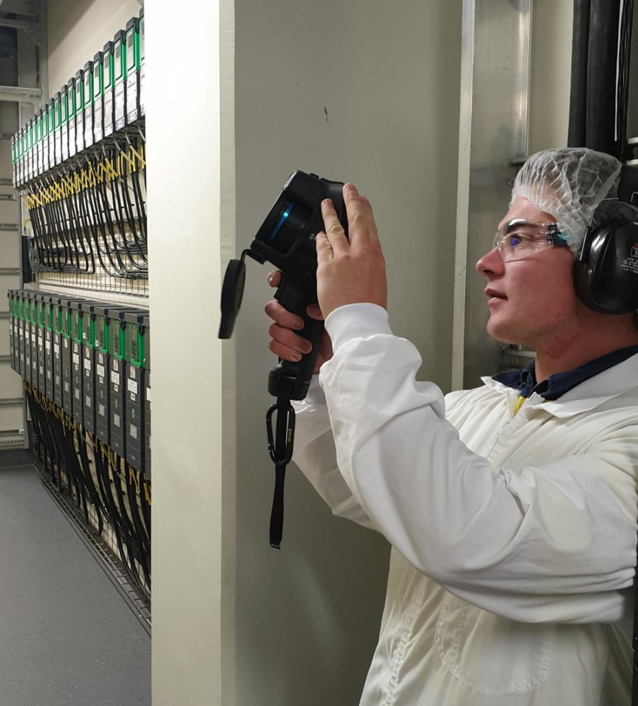
That’s where thermal imaging (thermography) comes in. It’s a non-intrusive, non-contact method that helps us spot issues you’d never see with the naked eye.
Using a specialised camera, we capture heat patterns in your electrical equipment. Abnormal heat is often the first sign that something’s not right – like loose connections, overloaded circuits, or failing components.
By detecting these problems early, we can fix them before they snowball into costly breakdowns, unplanned downtime, or even fire hazards.
Why Thermal Imaging Matters:
- Catch hidden faults before they cause equipment failure
-
Cut down on expensive reactive repairs
-
Extend the lifespan of your electrical assets
-
Reduce downtime and keep your business running smoothly
When should you get a thermal imaging check?
Routine checks should be part of your preventative maintenance plan, but they’re especially valuable:
-
After major changes or upgrades to your electrical system
-
If you notice burning smells, hot spots, or overheating equipment
-
After electrical failures or unexplained faults
-
Following a power surge or electrical storm
What can we check with thermal imaging?
-
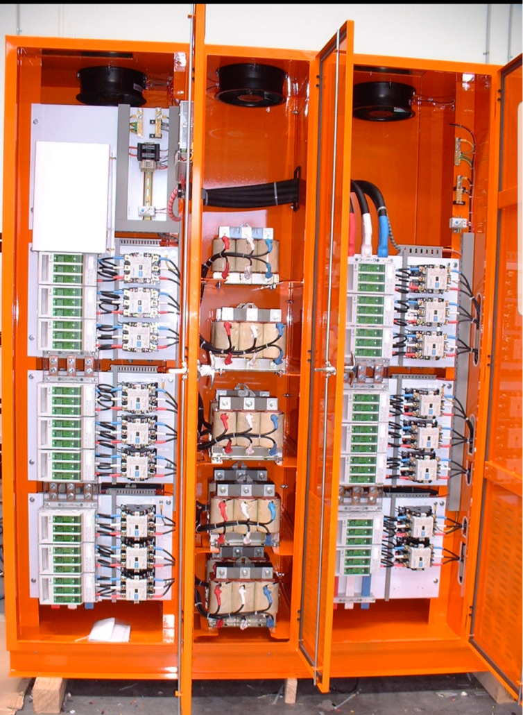
Electrical panels – detect hot spots from loose connections or overloads
-
Circuit breakers – identify faulty operation before failure or fire risk
-
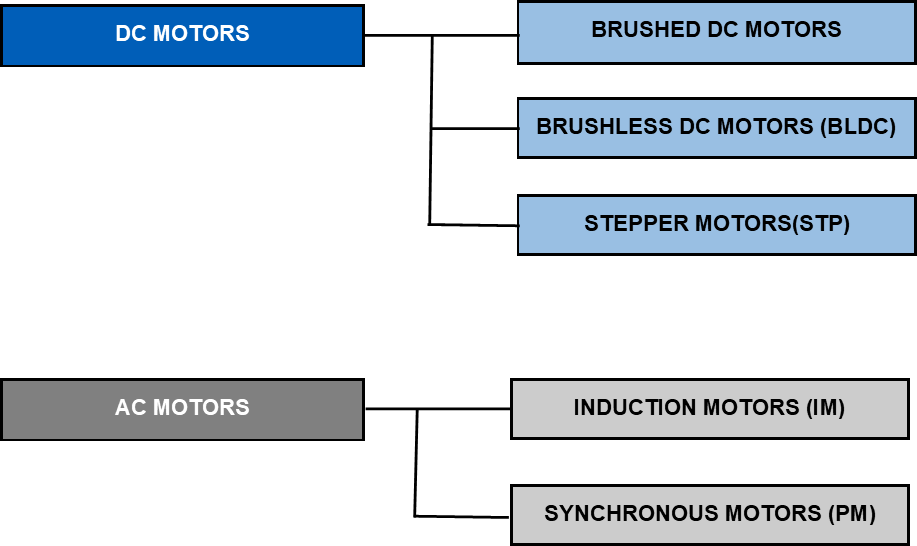
Motors – monitor bearings, windings, and components for wear
-
Switches – spot overload issues early
-
UPS systems – check battery health and wiring
-
Generators – ensure reliability of key components
Why Choose EAS?
The EAS team are trained and experienced in thermal imaging inspections, giving you peace of mind that your electrical systems are safe, efficient, and reliable.
Get in touch to book your thermal imaging check today – Drop us a line or give us a call on 07 834 0505